

Introduction
In industrial maintenance, quality control, and non-destructive testing (NDT), thorough internal inspections are essential for detecting cracks, corrosion, wear, foreign objects, and other defects before they lead to costly failures or downtime. Complex assets such as engines, turbines, heat exchangers, pipelines, gearboxes, castings, and pressure vessels often have multiple internal sections that cannot be examined effectively in a single continuous pass.
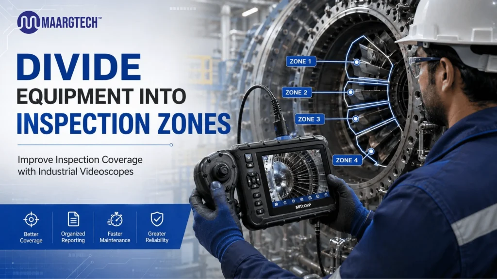
Dividing equipment into logical Inspection Zones provides a structured, repeatable approach. When combined with a high-quality industrial videoscope (also called a video borescope or remote visual inspection tool), this method improves coverage, documentation accuracy, efficiency, and consistency across inspections.
At MAARGTECH, we supply advanced yet economical Mitcorp videoscopes trusted by automotive, aerospace, power, petrochemical, and manufacturing teams across India and beyond. Here’s a practical guide to dividing equipment into Inspection Zones using a videoscope.
Why Create Inspection Zones?
Large or geometrically complex equipment creates challenges: limited access points, varying probe reach, different lighting needs, and the risk of missing critical areas. An unstructured inspection can lead to incomplete coverage, inconsistent reporting, or repeated insertions that waste time.
Defining clear Inspection Zones helps you:
- Systematically cover every critical area
- Match the right probe diameter, length, and articulation to each section
- Capture consistent images and videos for comparison over time
- Assign responsibility and track progress during team inspections
- Generate professional reports that map findings to specific zones
- Reduce the chance of blind spots
This approach turns a potentially chaotic process into a reliable part of your condition-monitoring and predictive-maintenance program.
Step-by-Step Guide to Dividing Equipment into Inspection Zones
1. Review Equipment Drawings and Identify Access Points Start with technical drawings, CAD models, or manufacturer manuals. Note all available ports, openings, spark-plug holes, inspection hatches, drain points, or removable covers. Map the internal geometry—bends, chambers, tubes, valves, blades, or cavities—and mark natural boundaries such as bulkheads, welds, or changes in diameter.
2. Segment Based on Geometry, Criticality, and Risk Divide the asset into logical zones according to:
- Physical sections (e.g., cylinder 1–6 of an engine, inlet/outlet of a heat exchanger, stages of a turbine)
- Functional criticality (high-stress areas, wear-prone surfaces, or previous failure locations)
- Accessibility and probe requirements (straight runs vs. complex articulations, small-diameter vs. larger openings)
- Inspection goals (general overview vs. detailed defect measurement)
Typical zone examples:
- Engine: individual cylinders, valve seats, piston crowns, exhaust ports
- Turbine: compressor stages, combustion chambers, turbine blades
- Heat exchanger or piping: tube ends, U-bends, header boxes, specific runs between flanges
- Casting or gearbox: specific cavities, gear meshes, oil galleries
Keep zones manageable—usually 4–12 zones depending on equipment size—so each can be inspected thoroughly without fatigue or loss of focus.
3. Assign Probe and Access Strategy to Each Zone Match Mitcorp videoscope capabilities to the zone:
- Probe diameter (e.g., 3.9 mm or 6 mm) that fits the access point
- Length sufficient to reach the farthest point in the zone
- Articulation type (2-way, 4-way, or 360° all-way) needed for navigation
- Lighting and imaging features for the expected environment
Plan the insertion path, any required guides or rigid sleeves, and the order of inspection (often from easiest or least contaminated zones to more challenging ones).
4. Establish a Standardized Inspection Sequence and Documentation Protocol Create a simple checklist or digital template that lists each Inspection Zone in order. For every zone record:
- Access point used
- Probe settings and articulation positions
- Still images and video clips with timestamps or annotations
- Observed condition (normal, anomaly description, approximate size/location)
- Any measurements if using advanced models such as the Mitcorp X3000 with 3D measurement
Tag files clearly (e.g., “Zone-3-Cylinder-2-Valve-Seat-2026-07-28”) so future comparisons are straightforward.
5. Execute, Review, and Refine Perform the inspection zone by zone. After completing a zone, briefly review captured media before moving on. At the end, compile a zone-mapped report. Over successive inspections, refine zone boundaries based on real findings and feedback.
Best Practices for Effective Zone-Based Videoscope Inspection
- Clean access points and the probe tip before each insertion to avoid contaminating the area or degrading image quality.
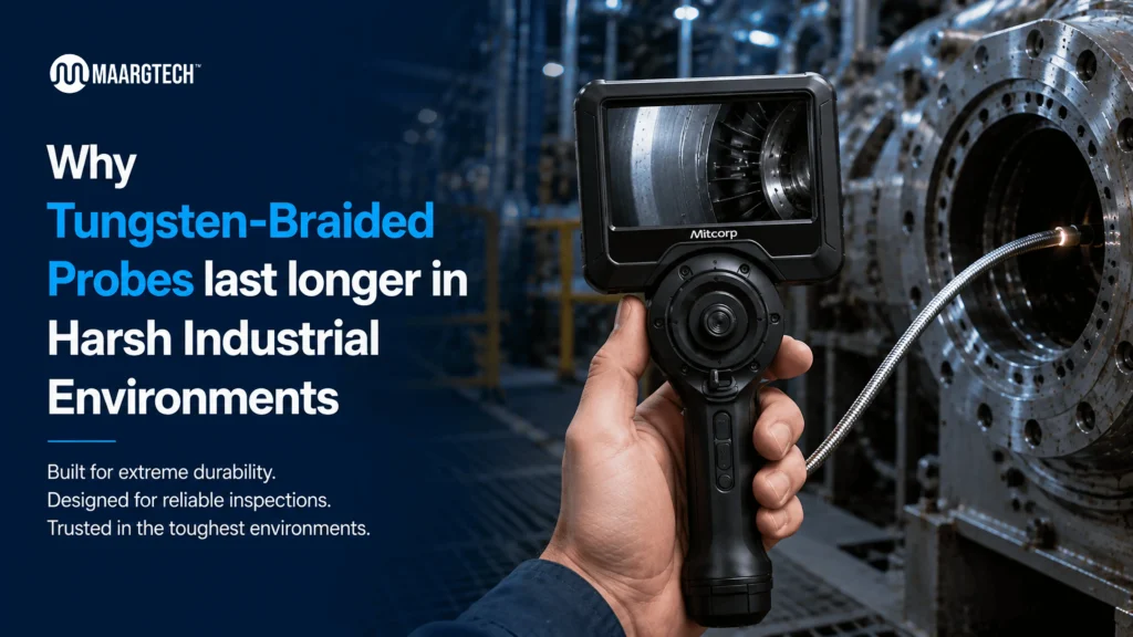
- Use tungsten-braided, IP67-rated probes for durability in harsh industrial environments.
- Leverage features such as image comparison, annotation, watermarking, and Wi-Fi transfer available on Mitcorp models (X2000 HD, X750 HD, X3000, PRSL 300) for efficient documentation.
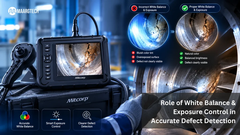
- Maintain consistent lighting and focus settings within a zone for comparable images.
- Train inspectors on the zone map so different team members produce consistent results.
- Combine zone inspection with other NDT methods when needed for confirmation.
Benefits for Your Maintenance Program
Structured Inspection Zones improve detection of early-stage defects, support trend analysis, shorten inspection times once the process is established, and strengthen compliance with internal quality or regulatory requirements. They also make it easier to prioritize repairs and demonstrate due diligence.
Choose the Right Videoscope for Zone-Based Work
MAARGTECH offers Mitcorp industrial videoscopes designed for precise, reliable remote visual inspection:
- X2000 HD and X750 HD for high-resolution imaging and excellent maneuverability
- X3000 with dual-camera and 3D measurement for quantitative assessment of defects within zones
- Flexible probe options in multiple diameters and lengths with robust articulation
These systems deliver the clarity, durability, and documentation tools needed to make Inspection Zone strategies practical and effective.
Ready to Improve Your Internal Inspection Process?
Dividing equipment into clear Inspection Zones transforms videoscope work from ad-hoc checks into a professional, repeatable system that protects assets and reduces unplanned downtime.
Contact MAARGTECH today for advice on the best Mitcorp videoscope for your applications, or request a demonstration and quote. Our team supports customers across automotive, aerospace, power, process, and manufacturing industries with advanced yet economical RVI solutions and reliable after-sales service.
Ready to Improve Your Inspection Process?
Explore MAARGTECH’s advanced industrial videoscopes to create effective Inspection Zone plans and detect defects with confidence.
📞 +91-97572 76307 | 📧 sales@maargtech.com
Frequently Asked Questions (FAQ'S )
How many Inspection Zones should I create for typical industrial equipment?
Most industrial assets (engines, turbines, heat exchangers, gearboxes, etc.) work best with 4–12 clearly defined Inspection Zones. Too few zones increase the risk of incomplete coverage, while too many can make the process unnecessarily time-consuming. The ideal number depends on the equipment’s size, complexity, and critical areas.
Can the same Inspection Zone map be reused for repeat or future inspections?
Yes — and it should be. Using the same zone boundaries and naming consistently allows direct comparison of images and condition changes over time. This is one of the strongest advantages of the zone-based method for tracking deterioration and supporting predictive maintenance.
Do I need special software to document Inspection Zones properly?
Not necessarily. Many Mitcorp videoscopes (such as the X2000 HD, X750 HD, and X3000) already include built-in tools for annotation, tagging, image comparison, watermarking, and file management. Simple organized folders with consistent naming (e.g., Zone-03-Cylinder-02) also work very effectively for most teams.
How do I decide the boundaries of each Inspection Zone?
Base the zones on a combination of physical geometry (chambers, stages, tubes, cylinders), functional criticality (high-stress or wear-prone areas), accessibility (probe diameter and articulation needs), and inspection goals. Start with equipment drawings, previous inspection records, and natural boundaries such as welds, bulkheads, or diameter changes.
Will dividing equipment into Inspection Zones actually save time, or will it make inspections longer?
Once the zone map and checklist are established, the method usually saves time overall. It reduces repeated insertions, prevents missed areas that require re-inspection, improves documentation speed, and makes findings easier to review and act upon. The first inspection may take slightly longer while setting up the process, but subsequent inspections become faster and more reliable.