
Introduction
In remote visual inspection (RVI) and non-destructive testing (NDT), simply viewing internal surfaces is often not enough. Inspectors need reliable dimensional data on cracks, pits, corrosion, wear, or other indications to support decisions on fitness-for-service, repairs, or remaining life. Visual assessment alone can lead to subjective judgments that vary between operators. Stereo Measurement in Videoscopes provides one of the established methods for obtaining quantitative measurements inside engines, turbines, pipelines, castings, heat exchangers, and other confined spaces without dismantling equipment.
This capability has become increasingly important as industries move toward data-driven maintenance strategies, Risk-Based Inspection (RBI) programs, and stricter regulatory compliance. Accurate sizing of defects helps avoid both under-repair (which risks failure) and over-repair (which increases unnecessary downtime and cost). At MAARGTECH, we supply advanced yet economical Mitcorp industrial videoscopes that support measurement capabilities suited to Indian industries in automotive, aerospace, power generation, petrochemical, and manufacturing. Understanding Stereo Measurement in Videoscopes helps quality and maintenance teams choose the right approach for accurate, repeatable results.
How Stereo Measurement Works
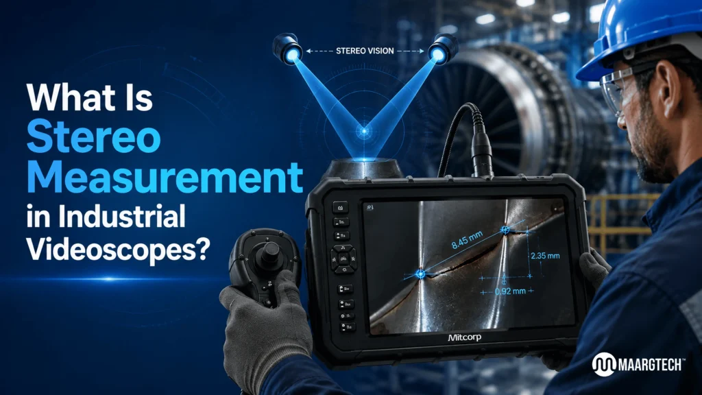
Stereo Measurement in Videoscopes relies on the same principle as human binocular vision: parallax. A specialized stereo tip adapter (or dual-lens optical tip) at the distal end of the insertion tube contains two lenses separated by a known fixed distance. These lenses capture two slightly offset views of the same scene—left and right images—onto the camera sensor.
The system’s processor uses the lateral shift (parallax) between corresponding points in the two images, combined with precise pre-calibrated optical geometry, to calculate the three-dimensional coordinates of selected points through triangulation. Inspectors place measurement cursors on key features (for example, the ends of a crack, the edges of a pit, or the height of a protrusion). The software then computes length, depth, height, area, or angles.
Because the calculation is based on the fixed baseline between the lenses and the observed disparity, Stereo Measurement in Videoscopes does not require the probe tip to be perfectly perpendicular to the surface. This flexibility is useful in complex geometries where perfect alignment is difficult. Accuracy depends on several factors: tip-to-target distance, image sharpness and contrast, proper focus, surface texture or features that aid point matching, and correct cursor placement by the operator. Closer working distances generally improve precision, while greater distances reduce it because the parallax effect becomes smaller.
Modern systems often generate a 3D point cloud or colored depth map from the stereo pair. This visual representation allows the inspector to verify that the reconstructed surface geometry looks realistic before finalizing measurements. Common measurement functions include point-to-point distance, point-to-line, depth or height relative to a reference plane, area calculation, and simple profile or cross-section analysis. The entire process—from freezing the image to obtaining a numerical result—can usually be completed in a short time once the probe is correctly positioned.
Key Advantages of Stereo Measurement
Stereo Measurement in Videoscopes offers several practical benefits for industrial RVI:
- Quantitative data supports objective decision-making rather than subjective visual estimates, improving consistency across different inspectors and inspection intervals.
- Measurements can be performed at various angles without strict perpendicularity requirements, making the method more forgiving in restricted-access situations.
- Results can be documented with annotated images, measurement values, and structured reports for compliance, Fitness-for-Service (FFS), remaining-life assessment, or Risk-Based Inspection (RBI) programs.
- It reduces the need for component disassembly, lowering downtime, labor costs, and the risk of introducing new damage during teardown.
- When properly applied, it provides repeatable results suitable for trending defect growth over successive inspections, supporting predictive maintenance approaches.
Compared with older comparison or shadow methods, stereo techniques generally deliver better three-dimensional capability and fewer geometric restrictions. However, advanced structured-light or phase-measurement systems can offer denser surface data and sometimes higher accuracy under ideal conditions. Stereo remains widely used because of its relatively straightforward operation, compatibility with many existing videoscope platforms, and lower complexity in certain field environments.
Practical Considerations and Best Practices
Successful Stereo Measurement in Videoscopes requires attention to technique and system condition:
- Keep the probe tip within the recommended working distance for the specific stereo tip (often in the range of tens of millimeters; always consult the manufacturer’s data for the particular model).
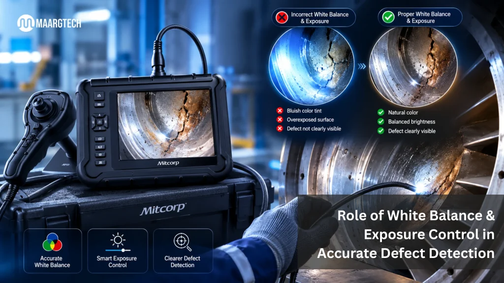
- Ensure the target is sharply focused and well illuminated with adequate contrast. Adjust LED intensity carefully to avoid overexposure or washed-out areas.
- Clean the optical tip thoroughly before use and verify system calibration or performance with a reference target or measurement verification block before critical inspections.
- Place cursors carefully on the same corresponding features in both stereo views. Operator skill and experience strongly influence final accuracy.
- Avoid highly reflective, featureless, or extremely dark surfaces when possible, as these can hinder reliable automatic or manual point matching.
- Maintain stable probe positioning during image capture to minimize motion blur.
- Train inspectors thoroughly on the specific system’s measurement software, limitations, and recommended procedures. Periodic refresher training helps maintain consistency.
Accuracy figures typically fall in the range of tens of micrometers under favorable conditions, but real-world performance varies with distance, surface quality, lighting, and operator technique. Always follow the manufacturer’s published accuracy curves and verification procedures rather than relying on ideal laboratory numbers.
Industrial Applications
Stereo Measurement in Videoscopes is applied across sectors where internal access is limited and quantitative data adds real value:
- Aerospace and aviation: sizing cracks, erosion, pitting, or foreign-object damage on turbine blades, vanes, combustion chambers, and other hot-section components.
- Automotive and powertrain: measuring wear, scoring, carbon deposits, or dimensional changes inside cylinders, valves, pistons, and gearboxes without engine disassembly.
- Power generation: assessing pitting, corrosion, material loss, or deposit thickness in boilers, heat exchangers, steam turbines, and gas turbines.
- Petrochemical and oil & gas: evaluating defects, corrosion, or erosion in pressure vessels, process piping, separators, and heat-transfer equipment.
- Casting, forging, and general manufacturing quality control: verifying internal dimensions, porosity, or defect sizes in complex components without destructive sectioning.
In each of these environments, the ability to obtain measurable data directly from the inspection view improves confidence in maintenance planning, safety assessments, and documentation for audits or regulatory reviews.
Stereo Measurement Alongside Modern Alternatives
Many contemporary videoscopes support multiple measurement modes on the same platform. Stereo Measurement in Videoscopes remains a proven and widely available option. At the same time, newer dual-view 3D systems or structured-light/phase-measurement technologies (available on select advanced models) can further improve speed, surface coverage, data density, or measurement confidence in demanding applications.
Choosing the right technology depends on the required accuracy level, typical defect sizes, inspection volume, access constraints, operator experience, and budget. Some systems allow switching between traditional stereo and enhanced 3D modes, giving flexibility for different inspection scenarios. MAARGTECH helps customers evaluate Mitcorp solutions—including models with advanced 3D and dual-view measurement capabilities—to match specific application needs with reliable, cost-effective equipment and responsive local support from our Mumbai-based team.
Conclusion
Stereo Measurement in Videoscopes transforms a purely visual inspection into a quantitative process by using dual-lens parallax and triangulation to determine real-world dimensions of internal features. When applied with proper technique, regular verification, and a clear understanding of its limitations, it delivers valuable data that supports safer, more efficient, and better-documented asset management.
As industries continue to emphasize predictive maintenance, digital records, and reduced unplanned downtime, measurement-capable videoscopes are becoming standard tools rather than optional upgrades. If your team needs accurate internal defect sizing as part of routine or critical RVI work, exploring measurement-ready systems is a practical next step.
Get the Right Industrial Videoscope for Your Inspection
Contact MAARGTECH for advanced industrial videoscopes and expert Remote Visual Inspection (RVI) solutions tailored to your application.
📞 +91-97572 76307 | 📧 sales@maargtech.com
Frequently Asked Questions (FAQ'S )
What is the basic principle behind Stereo Measurement in Videoscopes?
It uses two offset lenses to capture stereo image pairs and calculates dimensions via parallax and triangulation, similar to human depth perception.
How accurate is Stereo Measurement in Videoscopes?
Under ideal conditions (correct distance, focus, contrast, and cursor placement), accuracy is typically in the range of 0.01–0.1 mm or better, depending on the system and tip-to-target distance. Always refer to the manufacturer’s published accuracy data and verify performance with a reference target.
Does Stereo Measurement require a special tip?
Yes. A dedicated stereo optical tip adapter is normally required. Some advanced systems allow measurement with the same tip used for viewing or offer dual-view options that reduce the need to change tips.
When should Stereo Measurement in Videoscopes be preferred?
It is suitable when three-dimensional data is needed and access, cost, or operational constraints make more advanced structured-light systems less practical. It works well for many common defect-sizing tasks in aerospace, automotive, power, and process industries.
How can I improve reliability of measurements?
Maintain proper working distance and focus, ensure good lighting and surface contrast, verify system calibration regularly, place cursors carefully, keep the optical tip clean, and follow manufacturer-recommended operator training and procedures.