
Introduction
In industrial remote visual inspection (RVI), the ability of a flexible probe to navigate complex internal paths is critical for thorough examinations of engines, turbines, pipelines, castings, heat exchangers, and other components. One of the most important specifications that determines this capability is the Bend Radius in a Videoscope. Understanding the Bend Radius in a Videoscope helps inspectors choose the right equipment, prevent damage, and achieve accurate results across automotive, aerospace, petrochemical, power generation, and manufacturing sectors.
Defining Bend Radius in a Videoscope
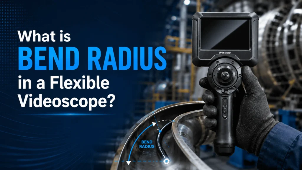
The Bend Radius in a Videoscope (also referred to as minimum bend radius) is the smallest radius to which the insertion tube or probe can be safely curved without causing permanent damage, kinking, buckling, or performance loss. It is measured from the center of the curve to the centerline of the probe.
A smaller Bend Radius in a Videoscope indicates higher flexibility, enabling the probe to pass through tighter turns and sharper corners. Exceeding this limit can buckle the insertion tube, stretch or break articulation cables, damage electrical wiring or fiber components, reduce image quality, or impair steering. Manufacturers determine the Bend Radius in a Videoscope based on probe diameter, materials such as tungsten braiding or polyurethane sheathing, and the internal arrangement of cables and sensors.
Typical values vary widely. Smaller-diameter probes (2–4 mm) may achieve radii as low as 6–15 mm, while more robust industrial probes (6–10 mm) often require 30–70 mm or greater. Always refer to the specific product data sheet for the exact Bend Radius in a Videoscope.
Why the Bend Radius in a Videoscope Matters for RVI
Industrial components rarely offer straight, unobstructed paths. Turbine blades, cylinder heads, boiler tubes, process piping, and castings contain elbows, offsets, restricted openings, and multiple direction changes. When the Bend Radius in a Videoscope is insufficient for the application:
- The probe may fail to reach the target area.
- Operators may apply excessive force, risking damage.
- Tip articulation can become limited after navigating several bends.
- Inspection coverage becomes incomplete, leading to missed defects.
Selecting a system with an appropriate Bend Radius in a Videoscope improves access, reduces downtime, extends equipment life, and supports reliable decision-making. At MAARGTECH we focus on matching Mitcorp videoborescopes and related RVI tools to real-world geometries so customers obtain both performance and value.
Factors That Determine the Bend Radius in a Videoscope
Several design elements influence the Bend Radius in a Videoscope:
Probe Diameter Smaller outer diameters generally allow tighter radii because less material must stretch or compress. Micro probes offer the most aggressive flexibility, while larger diameters prioritize durability, illumination power, and larger image sensors.
Construction Materials and Sheathing Tungsten-braided or multi-layer tubes provide excellent abrasion and crush resistance for industrial environments but can increase the minimum radius compared with softer urethane or nylon sheaths. The layout of articulation wires, light guides, and video cables inside the tube also plays a role.
Articulation Section versus Main Insertion Tube The distal bending section is engineered for controlled tip deflection (commonly 120–180° in two- or four-way systems). The longer insertion tube has its own Bend Radius in a Videoscope that must be respected during routing. Even if the tip articulates freely, forcing tight loops in the shaft can still cause damage.
Working Length and Friction Longer probes experience greater friction and potential cable stretch when passing multiple bends. This makes adherence to the stated Bend Radius in a Videoscope especially important on extended inspections.
Practical Effects on Inspection Quality and Equipment Life
Ignoring the Bend Radius in a Videoscope can produce several problems: localized buckling, permanent deformation of the tube, reduced or lost tip articulation, image distortion, uneven illumination, and difficulty withdrawing the probe. Over time these issues increase repair costs and reduce inspection reliability.
Conversely, matching the Bend Radius in a Videoscope to the tightest expected turn enables smooth navigation around pipe elbows, past turbine vanes, or into intricate castings. When combined with four-way or joystick articulation, this flexibility delivers comprehensive views that rigid borescopes cannot achieve. Pre-planning the insertion path and treating the manufacturer’s minimum radius as a firm limit helps operators avoid incomplete inspections and expensive repairs.
Selecting the Right Videoscope Based on Bend Radius
When evaluating flexible systems, consider the following:
- Compare the stated Bend Radius in a Videoscope against the tightest geometry in the component to be inspected.
- Balance diameter, working length, articulation range, IP rating, and temperature resistance with the required flexibility.
- Choose durable tungsten-braided construction for harsh industrial environments while confirming the Bend Radius in a Videoscope still meets application needs.
- Train operators to guide the probe gently and never force it beyond its rated limit.
MAARGTECH supplies reliable, cost-effective Mitcorp videoborescopes and complementary RVI solutions for customers in India and abroad. Our experience across automotive OEMs, aerospace, power, petrochemical, and research facilities allows us to recommend systems whose Bend Radius in a Videoscope aligns with actual inspection challenges.
Best Practices for Protecting the Probe
- Review the manufacturer’s minimum Bend Radius in a Videoscope before every job.
- Guide the probe carefully; never force it around sharp corners or create tight external loops.
- Avoid coiling the insertion tube tightly when storing or transporting the unit.
- Perform visual checks of the sheathing and test full articulation after demanding inspections.
- Store the videoscope in its protective case in a relaxed position.
Following these practices preserves both the mechanical integrity and the optical performance of the system.
Industry Applications Where Bend Radius Plays a Key Role
In automotive and casting inspection, probes must negotiate complex water jackets, oil passages, and internal cavities. In aerospace, access around engine stages and airframe structures demands controlled flexibility. Power and petrochemical plants require navigation through heat-exchanger tubes and process piping that contain multiple elbows. In each case the correct Bend Radius in a Videoscope determines whether the inspection can be completed efficiently and without damage to the tool or the asset.
Conclusion
The Bend Radius in a Videoscope is a fundamental performance parameter that directly affects access, safety of the equipment, and the quality of remote visual inspection results. By understanding this specification, matching it to the application geometry, and following proper handling practices, maintenance and quality teams can obtain reliable visual data from hard-to-reach areas while protecting their investment.
Whether the task involves engines, turbines, heat exchangers, or process equipment, selecting a flexible videoscope with an appropriate Bend Radius in a Videoscope is essential for efficient, damage-free RVI. Contact MAARGTECH for expert guidance on Mitcorp videoborescopes and other advanced yet economical inspection solutions tailored to your industry requirements.
Need the Right Videoscope for Tight Inspection Paths?
Contact MAARGTECH for expert guidance and find the ideal MITCORP industrial videoscope for your inspection requirements.
📞 +91-97572 76307 | 📧 sales@maargtech.com
Frequently Asked Questions (FAQ'S )
What exactly is the Bend Radius in a Videoscope?
The Bend Radius in a Videoscope (also called minimum bend radius) is the smallest radius to which the insertion tube or probe can be safely curved without causing permanent damage, kinking, buckling, or loss of performance. It is measured from the center of the curve to the centerline of the probe. A smaller value means greater flexibility for navigating tight turns inside industrial components.
Why is the Bend Radius in a Videoscope so important for industrial inspections?
Industrial parts such as engines, turbines, heat exchangers, and piping rarely have straight paths. The Bend Radius in a Videoscope determines whether the probe can pass through elbows, offsets, and restricted openings without getting stuck or being forced. Choosing the correct radius improves access, reduces the risk of equipment damage, and helps deliver complete, reliable inspection results.
What happens if I exceed the minimum Bend Radius in a Videoscope?
Exceeding the limit can cause the insertion tube to buckle or deform permanently, stretch or break articulation cables, damage internal wiring, reduce tip steering ability, and lower image quality. In severe cases the probe may become difficult to withdraw, leading to costly repairs and incomplete inspections.
How do I select the right Bend Radius in a Videoscope for my application?
Match the manufacturer’s stated minimum bend radius to the tightest turn expected in the component. Also consider probe diameter, working length, articulation range, and environmental protection. Smaller-diameter probes usually offer tighter radii, while larger industrial probes trade some flexibility for durability. At MAARGTECH we help customers choose Mitcorp videoborescopes whose specifications align with real-world geometries in automotive, aerospace, power, and process industries.
How can I protect my videoscope and avoid damaging it due to bend radius issues?
Always check the manufacturer’s minimum Bend Radius in a Videoscope before use. Guide the probe gently and never force it around sharp corners or create tight external loops. Avoid coiling the insertion tube tightly during storage or transport, perform regular visual checks of the sheathing, and test full articulation after demanding jobs. Following these practices significantly extends the life and reliability of the equipment.